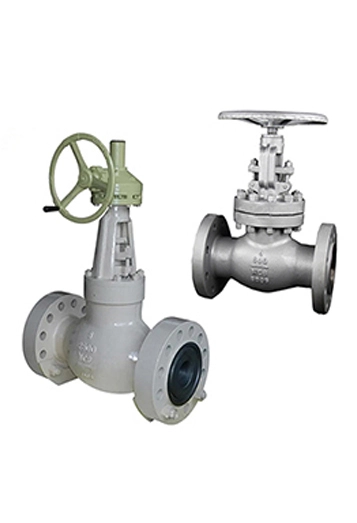
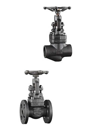
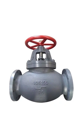
Globe Valve is a device which is widely used to deter an overflow in terms of volumes between the open and closed positions. It is best for on-off service. Globe Valve is widely operated in gas and liquid industries. Globe Valves are used to start, stop and regulate flows, and they are linearly actuated valves.The valve has an indication arrow which signs the direction, flow comes from. KFTE Globe Valves are designed and manufactured strictly to International Standards API 602, ASME B16.34, DIN3202 or Equivalent. Pressure Ratings from Class 150 to Class 2500, PN16 to PN420. Sizes Ranges from 1/2" thru 24". Ends Connections in Flanged R.F or RTJ, butt-weld. A wide range of materials are available from KFTE Globe Valve, including Carbon Steel, Low Temperature Carbon Steel, High Temperature Alloy Steel, Stainless Steel, Duplex & Super Duplex Steel.


1. Design and Structure:
Globe Valve: Features a spherical body with an internal baffle that splits the flow into two chambers. The disk moves perpendicular to the flow, often with a shorter stem stroke. The flow path is tortuous, creating higher resistance.
Gate Valve: Has a straight-through flow path with a gate-like disc that lifts completely out of the fluid path when open. The design is streamlined, requiring more turns to fully open or close due to the gate's vertical movement.
2. Function and Application:
Globe Valve: Ideal for throttling and regulating flow due to precise control of the disk position. Commonly used in systems requiring frequent adjustments (e.g., cooling, fuel systems).
Gate Valve: Designed for on/off control with minimal pressure drop when fully open. Suitable for pipelines (e.g., water, oil) where full flow or complete shut-off is needed.
3. Flow and Pressure:
Globe Valve: Causes a higher pressure drop due to the obstructed flow path. Effective in high-pressure systems but less efficient for unrestricted flow.
Gate Valve: Offers a straight, unobstructed flow with minimal pressure drop when fully open, optimizing efficiency in systems sensitive to pressure loss.
4. Operational Considerations:
Globe Valve: Provides better sealing and can handle frequent adjustments. Bidirectional flow is possible but often marked with a flow direction due to design.
Gate Valve: Not suitable for throttling (risk of erosion). Typically bidirectional but prone to seat/gate damage if left partially open.
5. Physical Dimensions:
Globe Valve: Compact in length but taller due to vertical disk movement.
Gate Valve: Longer in structure to accommodate the gate’s travel, requiring more installation space.
6. Maintenance and Durability:
Globe Valve: Seats may wear faster under throttling but are designed for it.
Gate Valve: Durable in full open/close use but vulnerable to leaks if eroded by partial operation.
1. Body
Function: The main outer casing that holds all internal parts. It has an inlet and outlet port, and the internal flow path is typically "S-shaped" to create resistance for throttling.
Material: Cast iron, stainless steel, brass, or alloy, depending on pressure/temperature requirements.
2. Bonnet
Function: A removable cover bolted or threaded to the body. It houses the stem and packing, ensuring a pressure-tight seal.
Types: Screwed, bolted, or pressure-sealed bonnets for different applications.
3. Disc
Function: The movable component that presses against the seat to block flow. It moves perpendicular to the flow direction via the stem.
Design: Often tapered or spherical for tight sealing. Materials match the seat to avoid wear.
4. Stem
Function: Connects the disk to the handwheel/actuator. Rotating the stem raises or lowers the disk to regulate flow.
Types: Rising stem (visible movement) or non-rising stem (common in compact spaces).
5. Seat
Function: A fixed ring inside the body where the disk seals to stop flow. Critical for leak-tight closure.
Material: Hardened metals for wear resistance.
6. Handwheel or Actuator
Function: Manual handwheel (for small valves) or automated actuator (pneumatic, electric) to rotate the stem.
7. Packing
Function: A seal (e.g., graphite, PTFE) around the stem to prevent fluid leakage along the stem.
Packing Gland: Compresses the packing to maintain the seal.
8. Gaskets
Function: Seal joints between the body and bonnet or flanges to prevent leaks.
9. Yoke
Function: Connects the bonnet to the actuating mechanism (e.g., handwheel) and supports the stem.
Secondary Components
Backseat: A secondary sealing surface on the stem and bonnet for maintenance safety.
Stem Nut: Converts rotational motion into linear motion for rising stems.
